Composite Solar Arch
Photo 1: The final arch with wind generator and antennas installed.
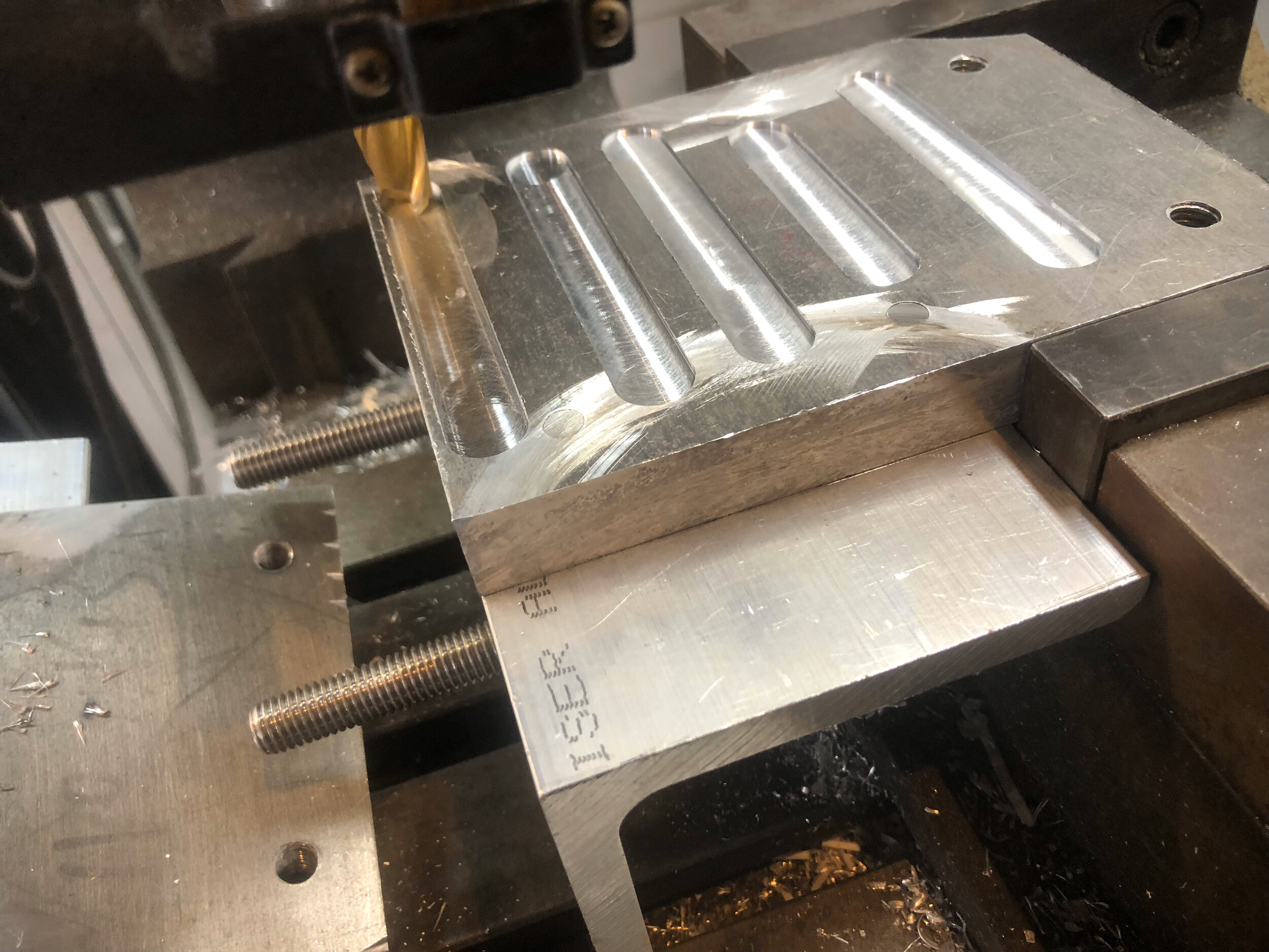
Photo 2: Machining the aluminium base plates.
Photo 3: A template to visually check the aesthetics.
Photo 4: Determining size of the top.
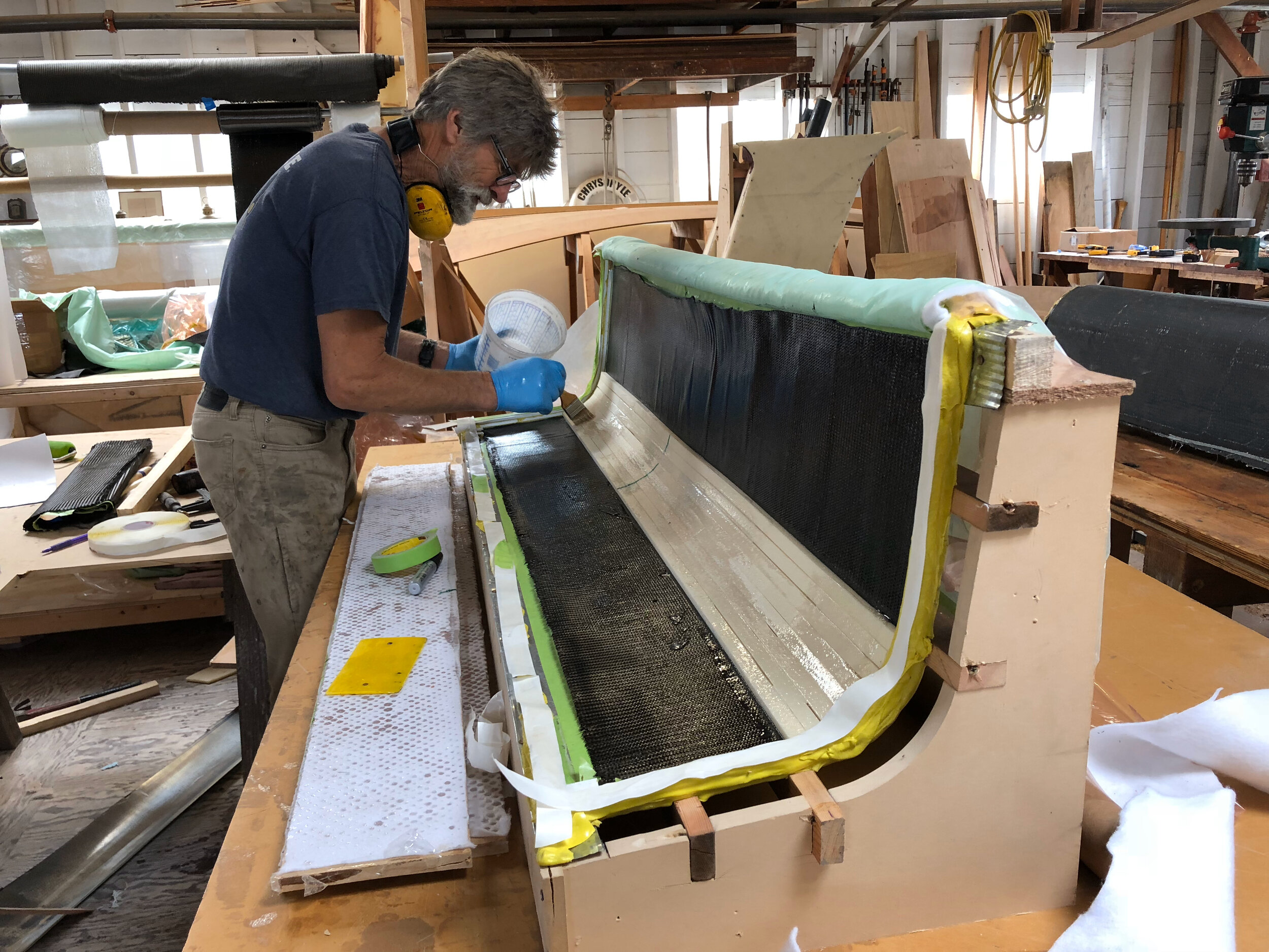
Photo 5: Moulding the outer radius.
Photo 6: Mould frame for the top.
Photo 7: Laminating the top.
Photo 8: Glueing the top radius inner in place.
Photo 9: Final fitting and glueing of the top outer radius.
Photo 10: Template for the pushpit welding, inner and outer skins for the top radius.
Photo 13: Blocks and cleats for davits, touch sensitive lights and speakers installed in place.
Photo 11: Transporting the fitted arch back to the workshop.
Photo 12: Filling and fairing before paint.
Photo 14: Hawse pipe and mooring cleat.
Why we changed from Stainless Steel
The boat already had a stainless steel solar arch and 5 solid solar panels which were installed in 2007. Although these panels performed well for the previous 12 years we decided that panels utilizing newer, lighter technology made sense. The older panels had solid frames around them to bolt to the tubular arch which needed modification to mount a new, thin flexible panel. Hence, we decided to build an entirely new composite structure.
This move had many advantages apart from just saving weight. Particularly, changing all our antenna cabling and adding capacity for more. We knew we wanted to install an Irridium Go system and trying to feed more cable into the stainless arch was almost impossible.
The other big plus we hope to never have to take advantage of is added stability. All boats similar to Denize ll suffer from having a relatively small vanishing angle of stability and a very large amount of stability when inverted. Our stainless arch weighed 100 kgs while the composite one weigh only 30 kgs. More importantly, in the event of being inverted, the composite arch provides almost 500 kilograms of buoyancy, and owing to how deep in the water, it would be, a reasonable righting moment.
Construction Details
The first consideration was how to attach the structure to the boat and how to deal with the aft mooring cleats which were originally on the deck. The simplest solution was to fabricate an aluminium base that would do both. Thanks to having the use of the workshop equipment at Spaulding Marine Center in Sausalito which included a mill and a lathe, making the brackets shown in the photo was easy and accurate. We were able to modify the existing cleats to allow them to be screwed on the arch. We removed the studs and made countersunk bronze inserts so there would be no electrolytic action with stainless steel screws.
After covering the deck with packaging tape, a cheap and effective mould release, a glass fiber/epoxy laminate was formed to the exact shape of the deck. This included the aluminium bases and a foam core. It also has the base for our spinnaker turning blocks. These can be seen in the photo which shows the rough template for the arch sides.
In order for the sides to be stiff enough to support the top without bending laterally they needed to be reasonably thick, but they did not have to have a solid foam core, in the same way that a steel “I” beam gets its stiffness by separating its top and bottom chords, we could get stiffness by having two side pieces separated by foam stringers. The side pieces of 10mm thick HD 80 PVC foam were first covered on what would be the “insides” with a vacuum bagged carbon fiber laminate, done on a vacuum table. Once this was done they were bent over a mould that would give them the slight curve aesthetics demanded. Once glued together they were strong enough to be able to support all the further construction without the carbon fibre on the outsides. These can be seen in the photo showing the levels being checked. They are at this stage glued to the base plates.
To avoid a lot of filling and sanding, especially of the internal corner where the sides meet the top, we moulded the shape of those corners. When only building one of something large female moulds are simply too expensive, they usually need a male plug to be made and that also needs filling and sanding! Since these moulds are only a 2 dimensional shape, almost flat turning to a radius and almost flat again they could be made from cheap shiny galvanised steel sheet laid into MDF patterns. The flat sections would be solid and the actual curves would have the same foam core as the sides. One mould would have the steel on an internal radius to make the outside of the finished curve and a second mould would have the steel bent around an external radius. The photo shows strips of foam being laid onto the wet carbon fiber outer skin, when these were in place the inner carbon was laid and then the hole lot vacuumed together.
The top also needed a mould, this was made using MDF rebated for pine stringers, covered in MDF and over laid with a single polyethylene sheet as a mould release. The MDF top had to be well coated with epoxy to ensure it was airtight as it would be the base for the vacuum bag. A single pin hole and it would not work. Quick work was required here as both the top and bottom skins where to be done in one operation. Our design had the solar panel sitting on a 25mm sheet of foam but needed deeper sectioned beams fore and aft to carry the weight of the dinghy, which though only a 60 kilogram dead weight, in nasty sea conditions could have an effective weight of 5 times that. We also have a very heavy wind generator on a tall pole, all this when it turns into a live load exerts considerable stress and strain. The beams are 40mm moulded and 80mm sided and have 6 layers of 300 grams/ m2 of uni directional “S” glass plus top and bottom. To add to the core shear resistance double bias carbon fiber links the top and bottom chords.
Assembling the basic components was done on the boat, while the top was a very good sail it was light enough to be easily handled. The sides where bolted down and checked alignment. Measuring the tops relative to the backstay for athwartships position and from the chainplates for fore and aft. When all were confirmed as perfect the inside corner sections were glued and clamped in place. The next day the outsides were done. After 48 hours curing the glue was deemed good enough to allow removal from the boat.
The elliptical forward and rounded trailing edges were added to the foam sides and then all sheathed in a laminate that was a mixture of carbon biaxial and unidirectionals and on the outside of the sides, for better impact resistance a 450 gram/m2 glass biaxial. Since we wanted a “knee” to increase resistance to athwartship flexing it made sense to incorporate these into speaker enclosures. While everything else on the arch was a foam/ fiber composite the knees are made of 19mm plywood and carbon fiber and the dinghy davits have a foam, Douglas Fir, foam core, again with carbon sheathing. The Douglas Fir takes the screws that hold the small genoa tracks and cars the dinghy is supported on.
The wind generator sits on a cantilevered aluminium pole that has several layers of Biaxial carbon sleeve laminated over it. The sleeve is non structural and is only to provide a way to make a water proof joint where the tube penetrates the arch side. All the antenna mounts were moulded in plastic mixing cups and have standard stainless steel bases mounted to them. All cables go though good quality glands inside the moulded mounts. The Cables run through a single conduit and are permanent with the exception of the later installation of the irrideum go antenna. All the others have water proof connectors at the top. No pulling cables when replacing antennas in the future.


