Engine-Driven Water Maker
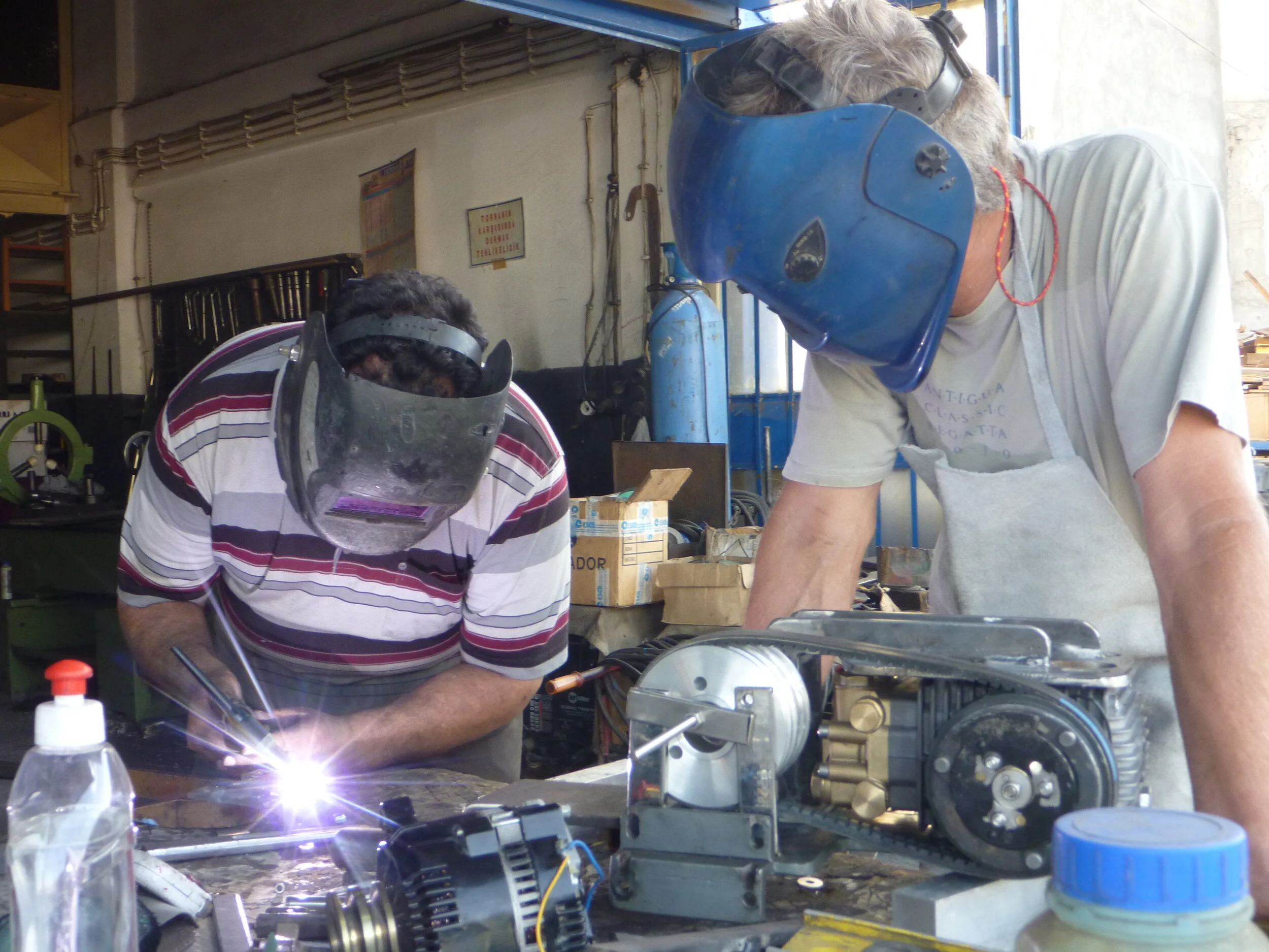
High pressure pump and high output large frame alternator share the same mounting plate. It is bolted to the engine and also has an extra engine mount to take the weight. This is positioned exactly in line with the center of the crankshaft which should be close to the axis on which the engine vibrates or moves against the inertia of the drive train. The purpose of this mount is to reduce the load on the engine to bracket connection not increase it!
Building the bracket. The mounting plates that bolt to the engine are complete and a temporary jig to hold the drive pulleys in place welded on. This meant all alignment of pump and alternator could be done in the workshop. The modifications to the electro mechanical clutch have been completed. Our good friend Attila is welding the base for the alternator. This automotive model did not do well and was replaced with the large frame one (shown in the top photo) in the Canary Islands.
Engine side view of the mounting.
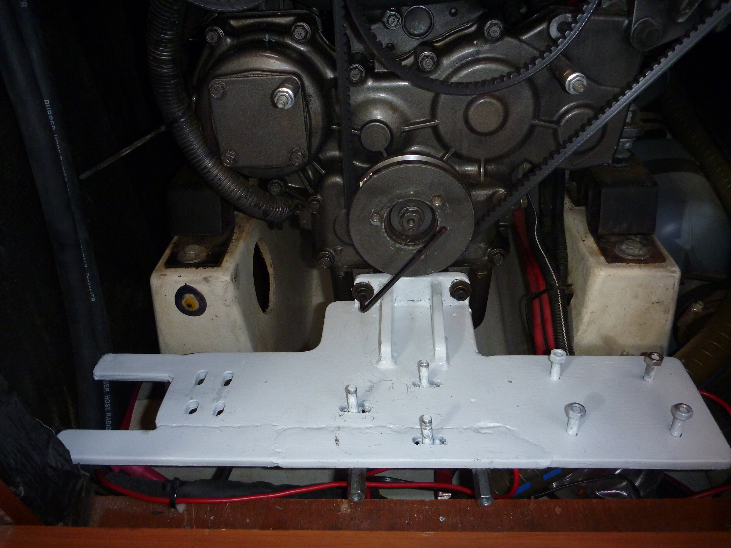
The mount almost finished. The weight of the pump bears on the lower plate but it is bolted in place with the top piece. Once in place the confined nature of the engine room prohibited access under the bracket so no bolts could be placed there.
The base plate bolted to the engine.
The lift (pre delivery pump) is mounted below the waterline since it is an impeller pump that may not self prime. The pressure switch illuminates a light showing delivery pressure on the remote control panel.
An admittedly crude looking valve mount has a simple cam that activates 1of 2 micro switches to show whether raw (salt) or product (flush) water is being directed to the pressure pump. This photo taken after 8 years of service, and before the micro switches had their contacts cleaned!
The membrane now lives in the Port Lazarette
A rather agricultural looking bracket holds the valve that directs the product water to either the tank or overboard via a skin fitting mounted in one of the galley sinks. We sample this water with a salt gauge before switching to the tank. Micro switches illuminate the appropriate warning lights on the control panel. Without these warning lights it was too easy to start the pump and inadvertently send water to the tank prior to testing.
The bracket shown above with the valve installed. Despite appearances all have worked flawlessly for 8 years!
Up and running, raising pressure to 60 bar increases output to 3 liters per minute but a lower pressure still gives a little over 2.5 liters and puts less strain on everything. Depending on both water temperature and salinity this can vary by over a liter per minute. This reading is in the relatively warm salty Med. In Alaska we were making 3.5-4 liters/min in some of the bays we anchored in. Pressure is adjusted with the valve on the panel. There is also a safety valve incorporated into the system that limits maximum pressure to 60 bar in the event of any failure to the adjusting mechanism.
Why an Engine-Driven Water-Maker?
Originally the boat did not have a water-maker. In 2007 Banu bought and installed a Katadyn 80 Watermaker which was reliable but produced far less water than was needed. Its power consumption was also quite high. We replaced this with a more efficient water maker which produces 150 liters an hour and is engine driven. SEAMAR Watermakers in Marmaris supplied the pump, the filter element, and the high pressure hoses while Peter made all the other parts installed the system.
System & Installation Details
The first thing to be done was modify an electromechanical clutch from an automotive air conditioner pump to fit the much larger, 30mm, shaft diameter of the high pressure pump. This was then fitted to the pump and a bracket designed that would both hold the pump and, diametrically opposed, a high output large frame alternator for our house bank charging. This was important because we didn’t want a large side load imposed on the engine crankshaft.
The pump installation was further complicated by not being able to access the underside of the bracket to bolt the pump in place. The need to accurately align and tension the belt between the driving and driven pulleys meant bolting the pump to the bracket first was not an option. The bracket was therefore made in two sections, the pumps weight would be taken by the plate underneath it but its position would be determined by a second plate bolted to that and fastened to the top of the pump. Careful construction and a little final milling made these two plates perfectly parallel and exactly the right distance apart. Small cams on the mounting bolts made it possible to accurately align the pump.
As with a lot of retrofitting of mechanical systems on a boat the biggest difficulty is trying to fit everything in place and run the cables and hoses to make it all work. This was especially true with this project. We wanted a reliable system that would be easy to operate and maintain. This meant a lot of components. We wanted a high capacity pre delivery pump near the supply seacock, two stage pre filtering of the salt water, easy flushing of the entire system, including the pre filters, with product water that had been further filtered through a charcoal membrane to ensure no chlorine could enter the system. We also wanted a flow meter and warning lights to show what the system was doing. In short, while home built we wanted all the bells and whistles of a high end manufactured unit. (for about 1000 euros)
Space restraints meant we had to separate the various components but all the valves could be mounted reasonably accessibly in the galley. The control panel could also be placed immediately aft of the galley in the port cabin. All the control valves were fitted with micro switches to activate warning lamps on the control panel. These show where the product water is going, salt or flush input water, pre delivery pressure and electromechanical clutch operation.


