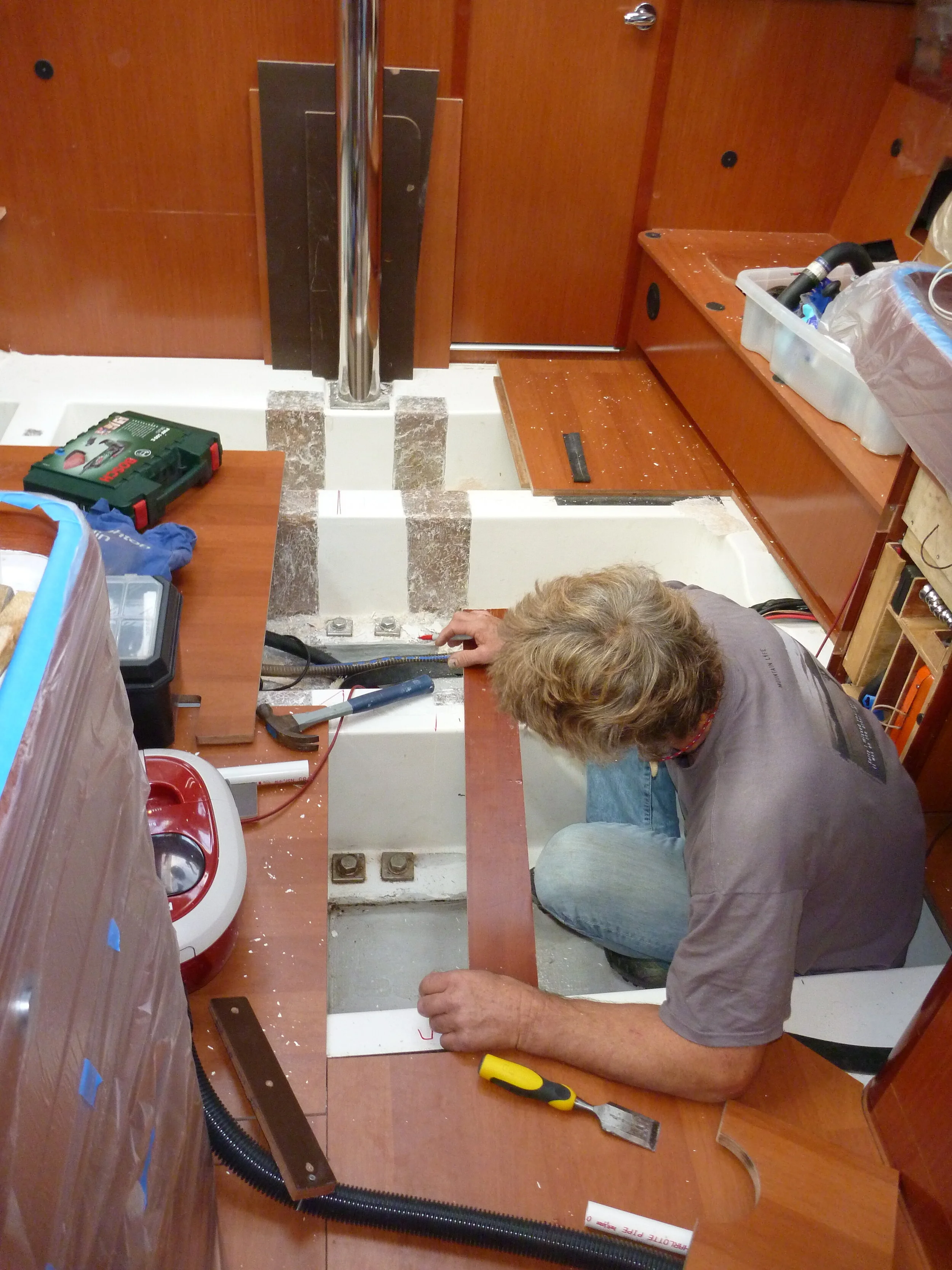
Ballast floors have been ground for the inboard face of the tanks.
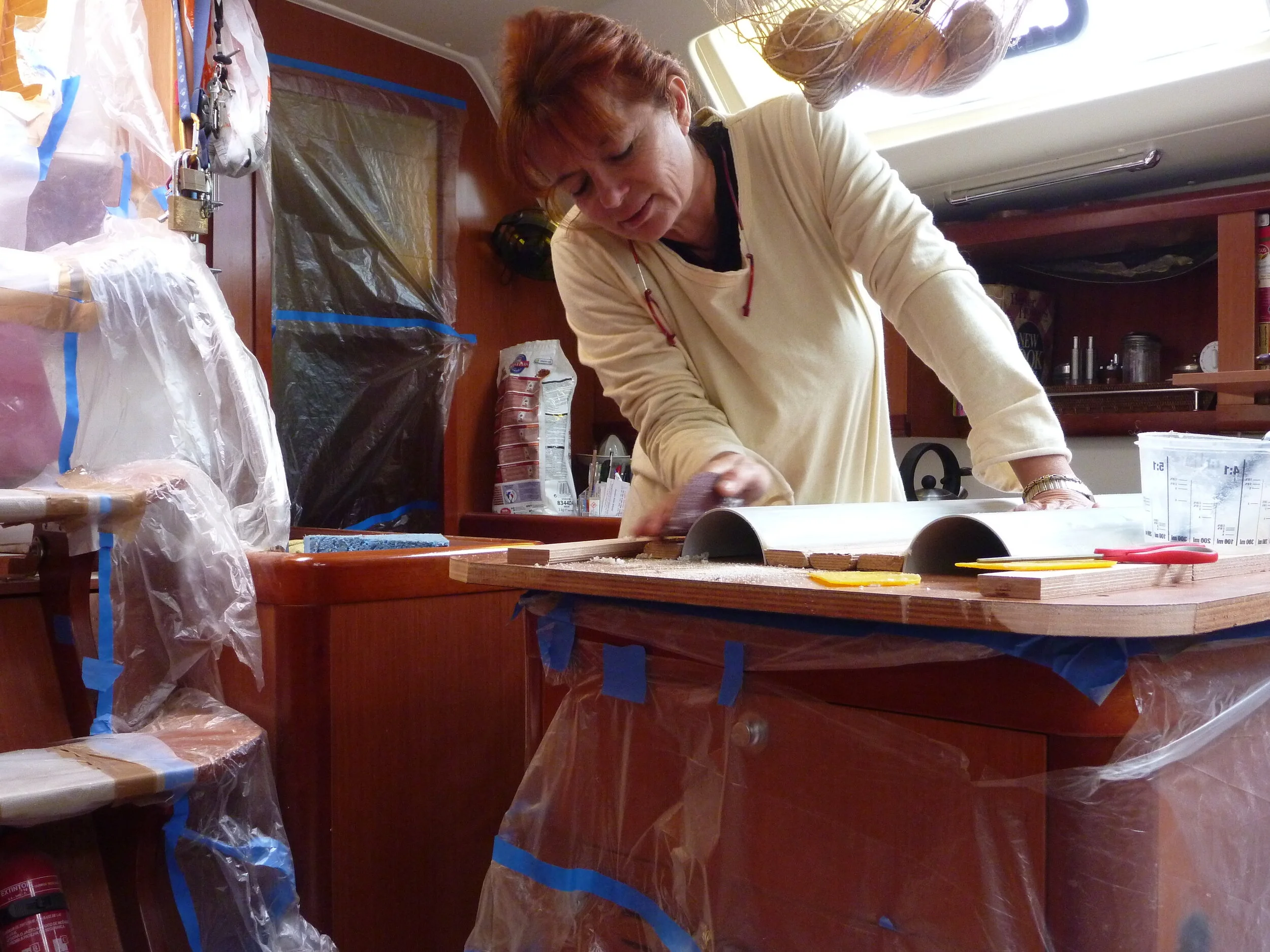
The mould for the cable trough.
Pre-pregging the glass for the tank liner.
Glassing the corners.
Glassing and baffles completed. Solid timber at the inboard sides of all and preglassed plywood at the outboard sides of the center tanks either side of the cable channel form the sealing faces for the tops.
Glassing the baffles before installation. To seal the end grain of the plywood where the baffles have their venting holes PVC pipe plugs with masking tape are laid into oversized cutouts filled with thickened epoxy.
Tank tops have been rebated for sealant, glassed, and sanded. They are ready to glue in place. This one for the center tank with the cable channel.
Applying sealant to the tank lid that goes over the cable channel.
Fastening the lids in place.
Integral Water Tanks
Why we moved the tanks
The original tanks were located in the ends of the boat. One under the “V” berth and the other under the aft port berth. As well as being in the worst possible position fore and aft this also placed them quite high up.
On our first West -East Atlantic crossing we had serious handling problems in the strong conditions (35-43 knots true wind / tight reaching) with the boat until the forward tank was completely emptied. The auto pilot was throwing the wheel from lock to lock to try to fix the “bow steer”. As soon as the tank was empty our speed went from 10.5 to 11.5 knots, and the pilot had to merely move the wheel a few degrees in either direction. Since the aft tank was already leaking a little, it made absolute sense to fix both problems concurrently and build in new tanks where they should have been to start with: under the cabin sole aft of the mast.
The Benefits
Taking the weight out of the ends of the boat has resulted in appreciable less “hobby horsing” in any waves when going upwind.
We no longer suffer with “Bow Steer”. While bow steer had been dangerous in heavy conditions it had also considerably limited the times we could fly a, especially shy, spinnaker. After the change we discovered that even in 25 Knots with quite rough conditions we could carry our biggest kite with the apparent on the beam. Previously in any waves 10 Knots had been scary with the wind on the beam and 15 downwind had been about the limit.
Center of gravity has been lowered considerably, the boat is more powerful upwind.
Multiple tanks are certainly safer in terms of potential contamination and having 6 similarly sized tanks makes calculating water usage on a passage very easy. It is much better to discover you are being a little too generous with water use when 1/6 of your supply is gone rather than 1/2 !
Construction Details
The first task was to remove all the existing sole, the port and starboard settees and the table. Since everything built into a boat is weight, nothing should ride for free. By this I mean that while the primary job of a tank is to hold a liquid it should have a secondary job strengthening and/or stiffening the hull.
The location of the new tanks meant we could effectively add a substantial beam on the centerline of the boat if we made the inboard side of the tank integral with the ballast floors. As the photo shows, the floors were ground back to glass so that a structural bond could be achieved with the 18mm plywood that would form the side. When epoxy coved and glassed in place, these panels, combined with the tank top would add a lot of stiffness to the hull. The tank tops would be glassed and glued to the plywood beam, the top of the floors and the hull at their outboard edges.
Whist using a hole saw to provide passage for the pipe work to be installed later we discovered that the liner which makes the ballast floors had been poorly laid up. Each little core sample easily split into three pieces. There was dry chopped strand glass between the reinforcement layers. To compensate for this more glass was used on the sides of the floors than would have been required to merely keep the water in.
As a major bundle of cables crossed the hull where the tanks were to be installed we used a split PVC drainage pipe as a mould for a channel to run them in. This was to be the only tricky part of this job, not actually making the channel, but adding additional vents to the two tanks affected , and ensuring the tops were properly sealed around them.
The outboard edges of the tanks were made by fitting a solid rail 50mm wide to the hull and then all of the plywood, liner and rail glassed with 450gsm double bias cloth. All the corners of the tanks got multiple layers and as already mentioned the sides of the ballast floors were given addition unidirectional glass to compensate for their poor initial layup.
The tank tops were cut from 18mm Okuame plywood, considerably lighter than the original sole, and glassed with 450gsm Double Bias cloth. All glass wet out with epoxy. Once all the glassing was complete several coats of epoxy were painted over all the tanks. As a shield to possible capillary action I like to have a continuous film of resin over all areas that have been jointed. This is probably overkill in a water tank but definitely sensible for diesel, so I do the same for all. No one will ever complain if they don’t leak.
All the skin fittings for fillers and vents were installed next. These were machined from acetal delrin and had “O” ring grooves on their sealing sides but would be installed with both sealant and “O” ring. The outlets are stand pipes, so that in the event of a hose failure the tanks will not empty.
Normally I would simply glue the tops down with epoxy, but Banu’s frequently voiced fear of leaks made me go one step further. A rebate was machined into the lids to take a bead of 3M 5200. I don’t recommend doing this as it is fraught with difficulties. Biggest is that the amines in many epoxy hardeners prevent polyurethanes from curing. Making sure that enough glue is used to connect both faces of the joint but not enough for it to spread to the bead of 5200 is the tricky calculation. As it happened we must have got it right since after 8 years all is still water tight.
Since building these tanks I have used expanded PTFE tape ( see the section on built in diesel tank) and would never use polyurethane sealant again. For permanently fitted tops the tape and epoxy would provide a perfect solution. The tape sealing the top and the glue giving structural unity for the tank to be part of the boat.


